Reassembling the Pioreactor
- Top faceplate version 1
- Top faceplate version 2
Step 1: Necessary parts #
Newer versions of the top faceplate will come with risers (2x) to secure the fan to the faceplate. See Version 2 tab for assembly instructions.
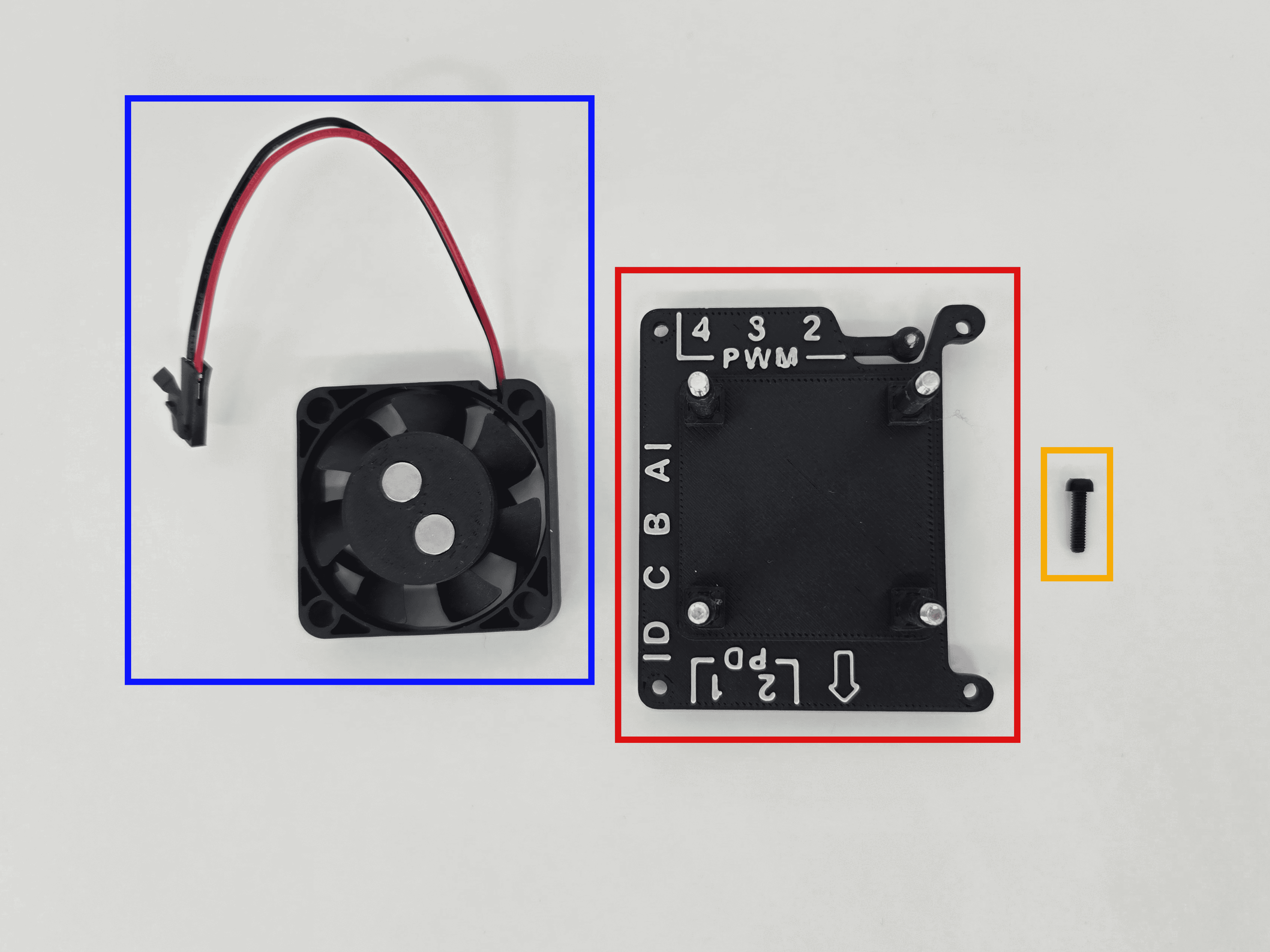
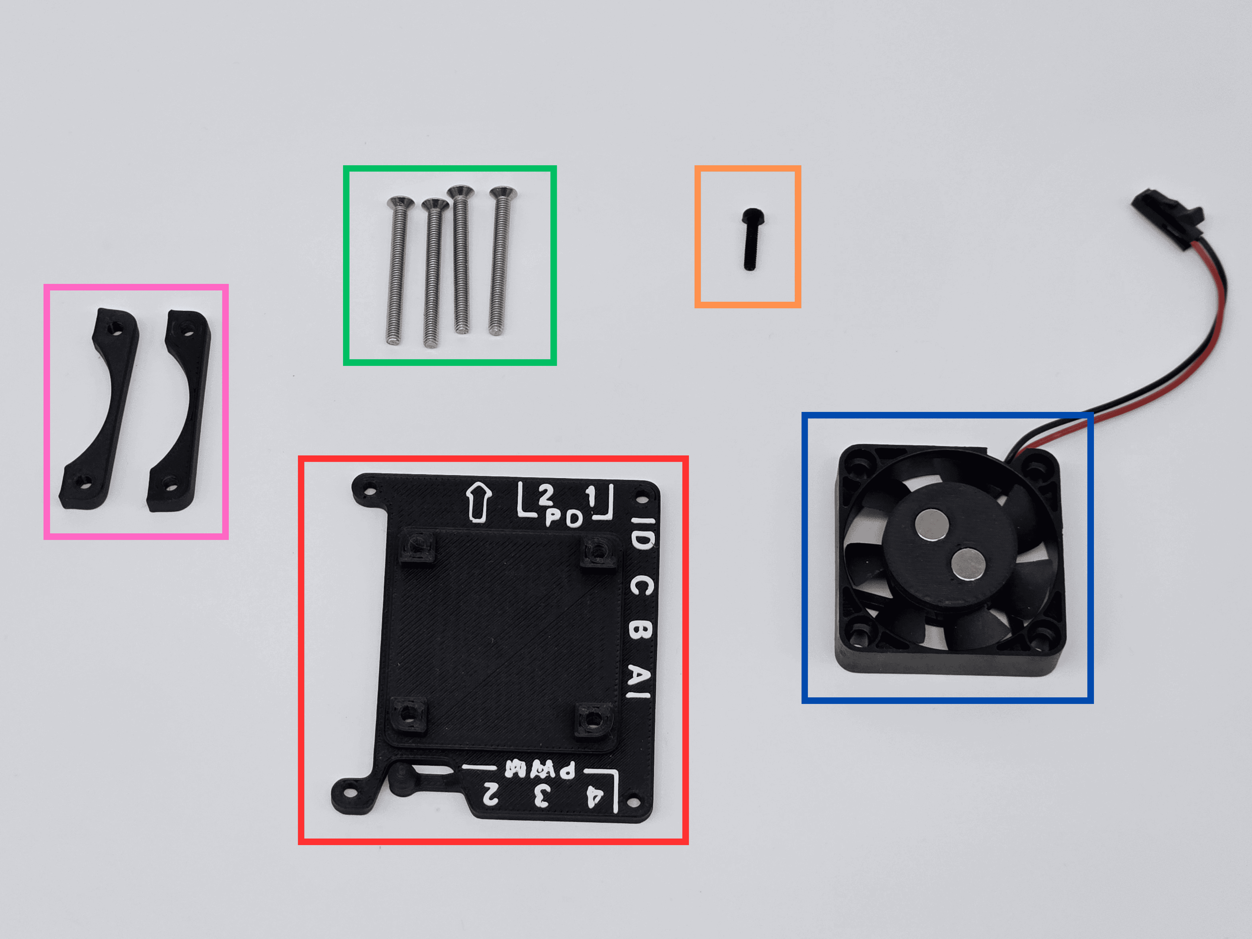
- For this version, you will need:
- Fan
- Top faceplate (will have 4x 30mm screws in it)
- M2.5 10mm screw (1x)
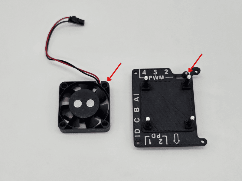
The fan and top faceplate come assembled - leave them together. If they are not assembled, attach the fan onto the faceplate with the cable oriented toward the side labelled "PWM".
Step 2: Securing the vial holder #
-
Push the fan onto the top faceplate, orienting it such that the wire is pointing towards the button.
-
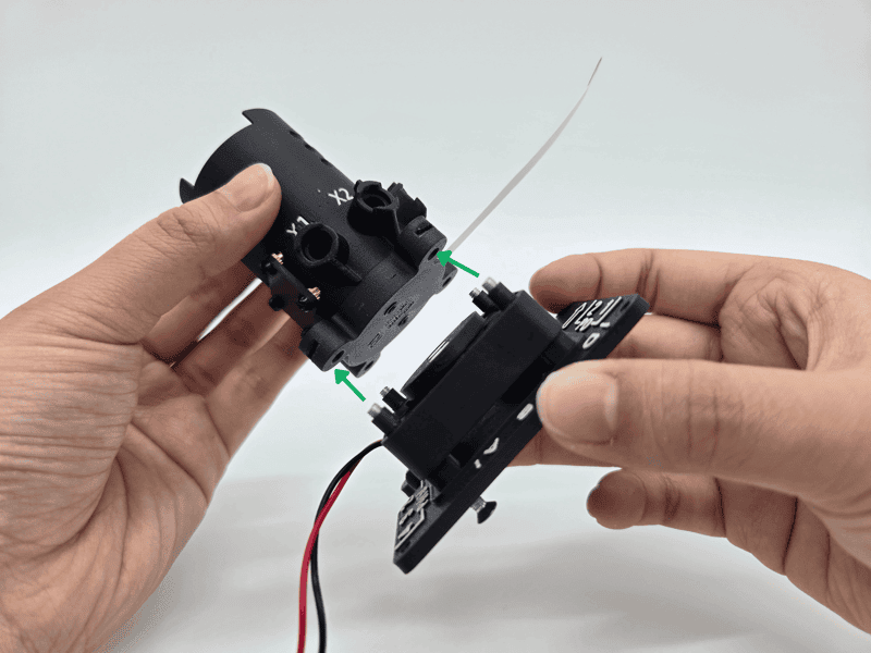
Place the vial holder on top of the four ends of the 30mm screws. The screw ends should fit into four holes on the bottom of the vial holder. The flat flex cable should follow the arrow on the faceplate.
-
Holding it together, finish screwing the M3 30mm screws on the bottom of the faceplate. The screws will enter square nuts in the vial holder. Do not overtighten.
cautionYou should not feel resistance when tightening the screws into the square nuts. If you encounter resistance, unscrew partially and inspect the end of the screw for any plastic debris.
-
The screw heads will be flush with the faceplate, and there should be no screw threads showing between the vial holder and the faceplate.
Step 3: Button extension #
The top faceplate comes with a button extension to provide easier access to pushing the button.
- Flip over the assembly.
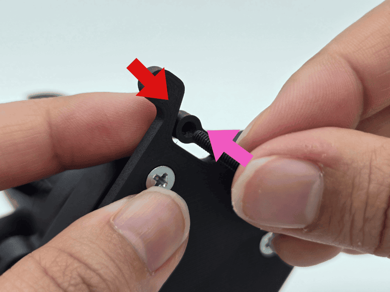
- Insert the 10mm screw into the hole under the button extension.
- Place one finger behind the extension and apply torque with the other hand until the screw is secure in the hole. This may require some force. Once established, you can use a screwdriver to finish screwing it in until you feel sufficient resistance. Don't over-tighten!
Step 4: Putting it all together #
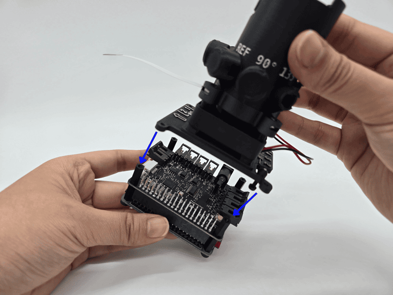
- Place the vial holder assembly onto the Raspberry Pi/HAT's corners. The GPIO pins align with the side notch of the faceplate.
- Using the M2.5 6mm screws, attach the top and bottom pieces in each corner.
- Check that the screw for the button extension is in the right position and not prematurely compressing the button under it (you should feel a "click" when pressing the button extension). Temove the top and screw in the M2.5 10mm screw more if you detect a problem.
- Open the flat flex cable connector on the HAT by pulling the tabs outward, like done previously. Insert the flex cable copper-side up.
- Push the tabs inward to secure the flex cable.
- Insert the stirring power connector into PWM channel 1 (unlabelled).
- Continue to the next page.
Step 1: Necessary parts #
- For this version, you will need:
- Fan
- Top faceplate
- M2.5 10mm screw (1x)
- 30mm screws (4x)
- Risers (2x)
Step 2: Attaching the fan to the top faceplate #
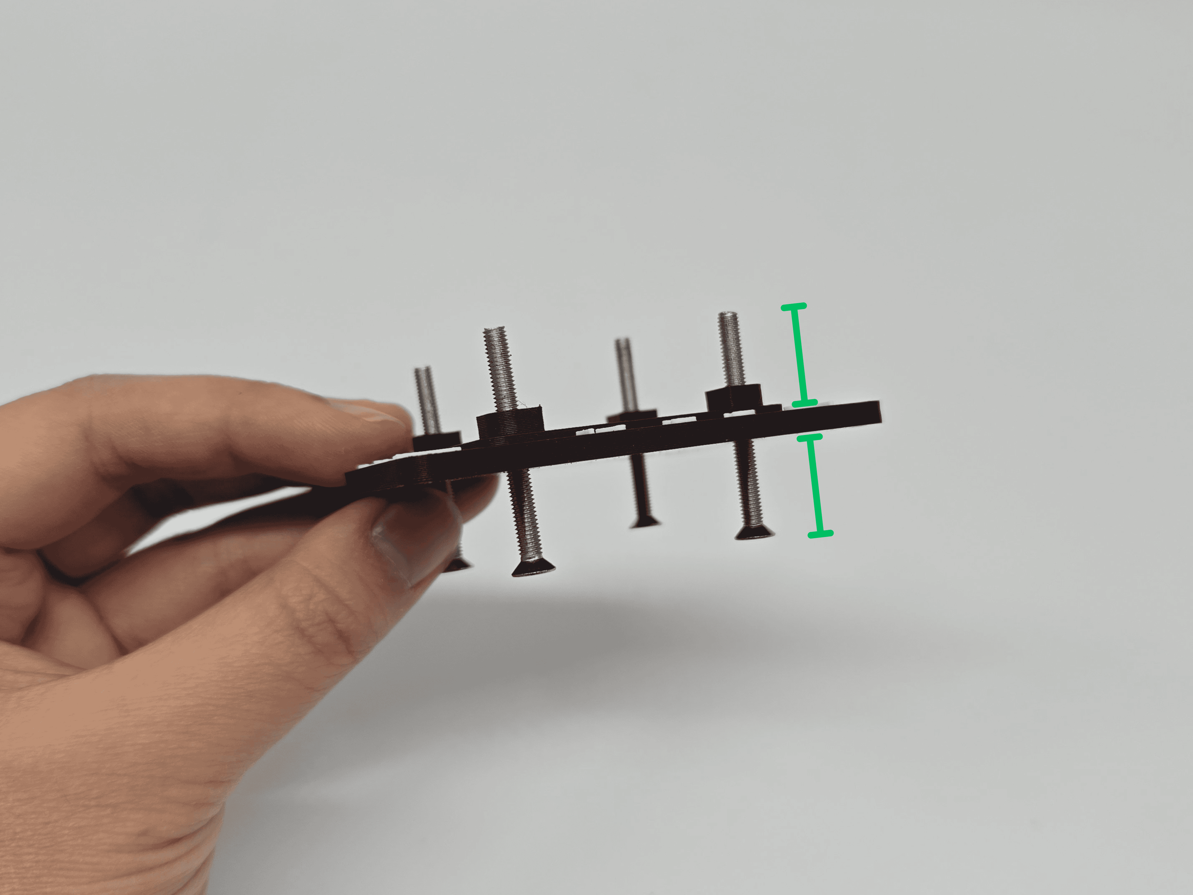
- Screw the 30mm screws about halfway into the bottom of the top faceplate.
- Push the fan onto the top faceplate, orienting it such that the wire is pointing towards the button.
- Align a riser onto the edge of the fan, such that the fan is sandwiched between it and the top faceplate. Place it along the same edge as the PWM labels.
- Holding the stack firmly, screw the 30mm screws into the risers such that screws poke through the top of the riser by ~2-3 mm. Repeat for the second riser on the opposite side of the fan.
Step 3: Securing the vial holder #
-
Place the vial holder on top of the four ends of the 30mm screws. The screw ends should fit into four holes on the bottom of the vial holder. The flat flex cable should follow the arrow on the faceplate.
-
Holding it together, finish screwing the M3 30mm screws on the bottom of the faceplate. The screws will enter square nuts in the vial holder. Do not overtighten.
cautionYou should not feel resistance when tightening the screws into the square nuts. If you encounter resistance, unscrew partially and inspect the end of the screw for any plastic debris.
-
The screw heads will be flush with the faceplate, and there should be no screw threads showing between the vial holder and the faceplate.
Step 4: Button extension #
The top faceplate comes with a button extension to provide easier access to pushing the button.
- Flip over the assembly.
- Insert the 10mm screw into the hole under the button extension.
- Place one finger behind the extension and apply torque with the other hand until the screw is secure in the hole. This may require some force. Once established, you can use a screwdriver to finish screwing it in until you feel sufficient resistance. Don't over-tighten!
Step 5: Putting it all together #
- Place the vial holder assembly onto the Raspberry Pi/HAT's corners. The GPIO pins align with the side notch of the faceplate.
- Using the M2.5 6mm screws, attach the top and bottom pieces in each corner.
- Check that the screw for the button extension is in the right position and not prematurely compressing the button under it (you should feel a "click" when pressing the button extension). Temove the top and screw in the M2.5 10mm screw more if you detect a problem.
- Open the flat flex cable connector on the HAT by pulling the tabs outward, like done previously. Insert the flex cable copper-side up.
- Push the tabs inward to secure the flex cable.
- Insert the stirring power connector into PWM channel 1 (unlabelled).
- Continue to the next page.