Wetware assembly
Step 1: Inserting the O-rings #
note
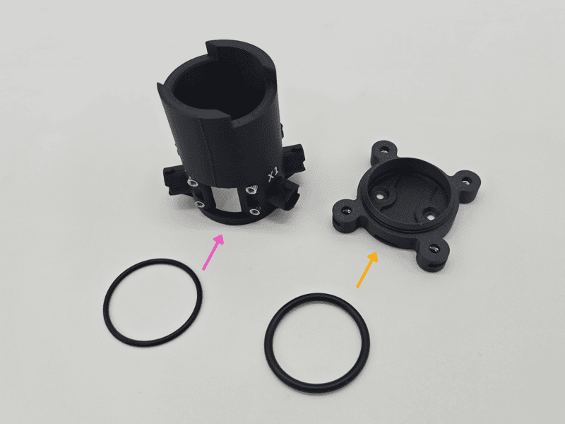
The vial holder of the v1.1 comes in two halves; a top vial holder and a bottom vial holder. Both have sections to insert O-rings for a more secure hold on your vials and increased protection against leaks. The thinner O-ring (#024) fits into the top piece. The thicker O-ring (#121) lines the bottom piece.
The #024 O-ring has been switched to a version with an X-shaped cross section in recently shipped v1.1 Pioreactors.
- The O-rings are pre-lubricated with a silicone-based lubricant. If needed, remove any excess lubricant from the O-rings.
- The top vial holder has a groove within the body where the thinner #024 O-ring sits. Carefully insert the O-ring using your fingers. Make sure to not twist the O-ring.
- Run your finger inside the vial holder, pushing the O-ring into place to ensure a snug fit.
- The bottom vial holder has a groove for the thicker #121 O-ring. The O-ring will sit between the base of the holder and the heater PCB. Carefully insert the O-ring using your fingers. Make sure to not twist the O-ring.
- Push the O-ring into place to ensure a snug fit.
Step 2: Attach the window cover #
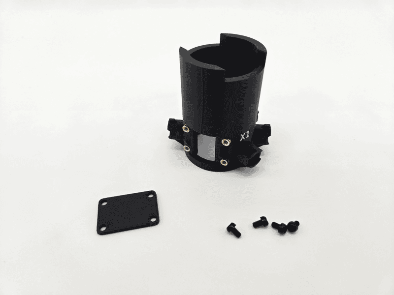
- Place the window cover over the window. It should fit snugly.
- Attach it using four M2.5 4mm screws.
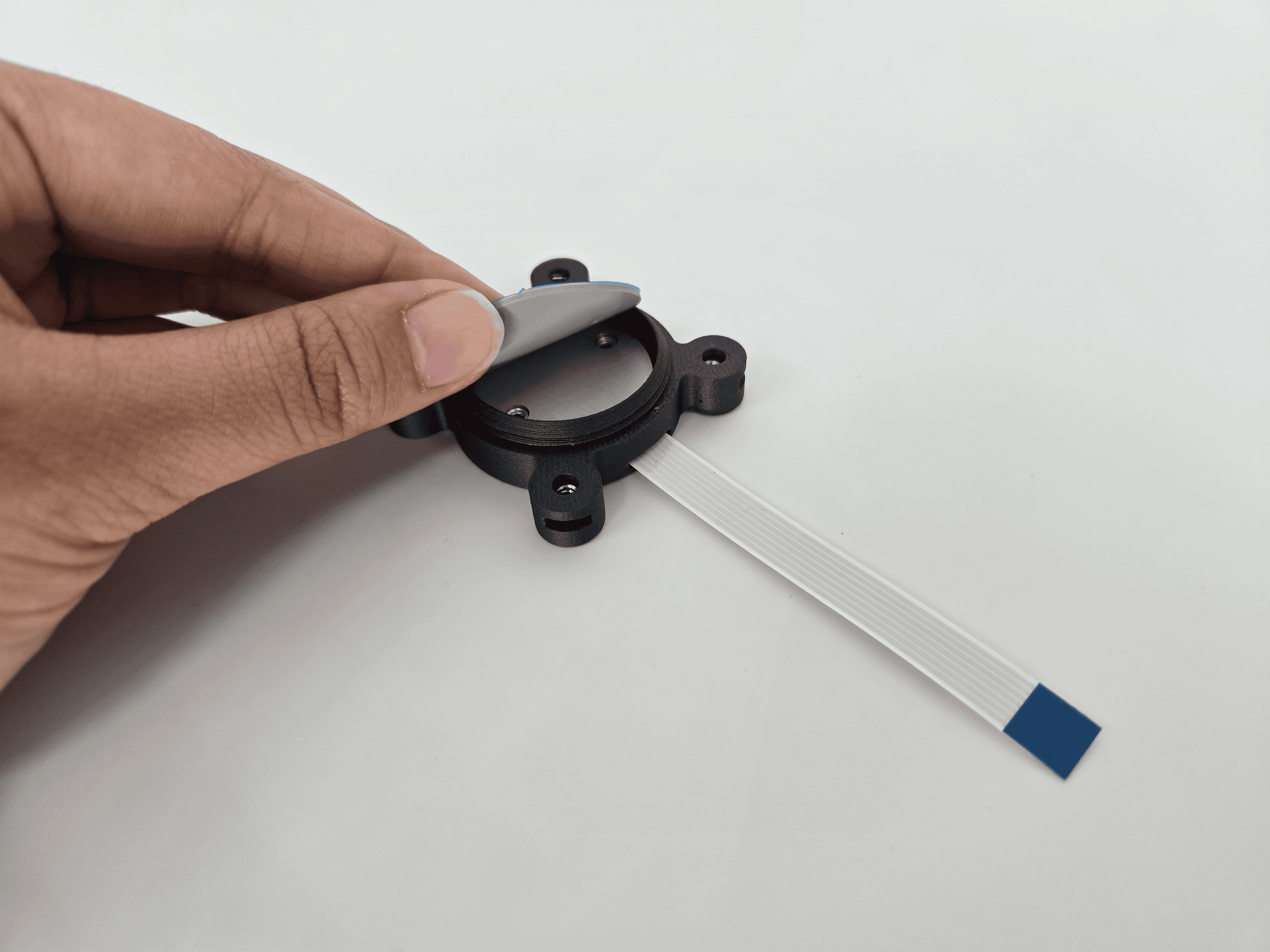
Step 3: Connect the flex cable #
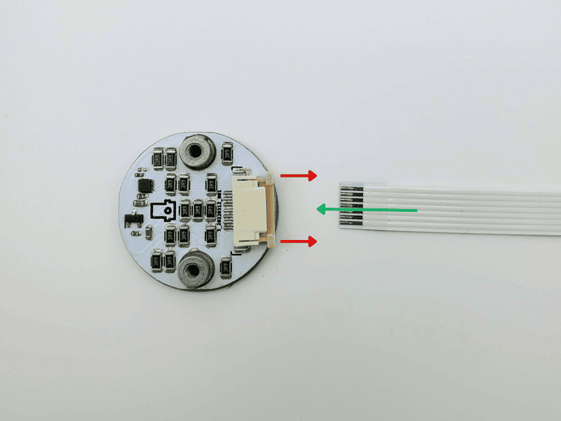
- On the heater PCB, locate the white-&-beige cable connector, pull the beige-colored tabs outward to open it.
- Insert the flex cable blue side down, copper side up, into the cable connector.
- Then push the beige tabs back in to secure the flex cable.
Step 4: Place and secure the heater PCB #
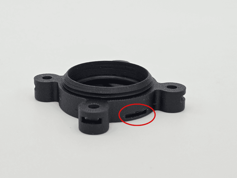
- Insert the other end of the flex cable below the O-ring and into the groove. Pull it through.
- Apply pressure on the back of the heater PCB so that it lies flat on the O-ring. Maintain this pressure for the next steps.
- While maintaining pressure, flip the holder and insert the two M2.5-CS 5mm screws into the holes - don't tighten fully yet.
- While maintaining pressure, take turns screwing each in until both are reasonably tight, and the heater PCB is securely attached to the bottom vial holder.
Step 5: Placing the heating pad #
- Remove the clear plastic from one side of the thermal pad. This exposes a sticky side on the thermal pad.
- Place on the flat (aluminum) part of the heating PCB. Lightly apply downwards pressure to secure it and remove any air bubbles trapped..
- Remove the blue protective plastic on top of the thermal pad.
Step 6: Complete the vial holder #

- Screw the top and bottom vial holder sections together so that the IR label is positioned above the flat-flex-cable.
- Set this aside and proceed to the next page.